IAN
Seasoned Member
Hi Members.
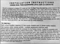
Enclosed are the istallation instructions made by Casper electronic part number 109096 modules kit to prevent some defect messages on the XLR cluster, for the installation of some after market shocks. additionals photos are enclosed to explain the installation.
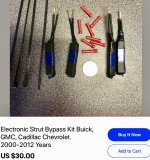
The next photo is the modules It self , the grey ones with 2 pins/cavities are to be put into the connector, removed from the solenoids (no longer required ) of each Mag.shocks.
The Black ones with 3 pins/cavities are to be put in the connectors removed from the suspension sensor.
![5 Product[1] (5).jpg 5 Product[1] (5).jpg](https://www.xlr-net.com/forums/data/attachments/5/5375-e1dadeaa0c6fd11f07cd3ac7e940028e.jpg?hash=4dreqgxv0R)
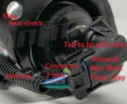
The following photo is the solenoid attached on the shock, it is of a rear XLR Mag.shock, that give you an idea of what it is.
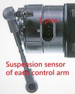
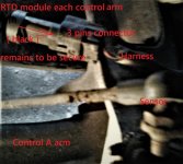
The suspension sensor is a small round devise that its linkage is conected with the lower control arm. The connector has to be removed by pulling away the locking tab and then the black module 3 pins/cavities has to installed on the connector.
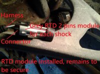
Here is a grey module installed on the connector, if you feel that it would not want to get in with a light pressure then turn it around and it should works, when you feel that its moving in then push it way in.
To secure it, use the tie wrap supposed included with the kit, (mine were not) when ordering it ask to make sure that they are really included.
Now the black module installed
Finally the job is completed.
The present methot I have used, is for a DIY with no hoist, or air gun ratchet....just some simple ordinary tools.
My next thread will be the road test.
IAN whala.
Enclosed are the istallation instructions made by Casper electronic part number 109096 modules kit to prevent some defect messages on the XLR cluster, for the installation of some after market shocks. additionals photos are enclosed to explain the installation.

The next photo is the modules It self , the grey ones with 2 pins/cavities are to be put into the connector, removed from the solenoids (no longer required ) of each Mag.shocks.
The Black ones with 3 pins/cavities are to be put in the connectors removed from the suspension sensor.
![5 Product[1] (5).jpg 5 Product[1] (5).jpg](https://www.xlr-net.com/forums/data/attachments/5/5375-e1dadeaa0c6fd11f07cd3ac7e940028e.jpg?hash=4dreqgxv0R)
The following photo is the solenoid attached on the shock, it is of a rear XLR Mag.shock, that give you an idea of what it is.

The suspension sensor is a small round devise that its linkage is conected with the lower control arm. The connector has to be removed by pulling away the locking tab and then the black module 3 pins/cavities has to installed on the connector.

Here is a grey module installed on the connector, if you feel that it would not want to get in with a light pressure then turn it around and it should works, when you feel that its moving in then push it way in.
To secure it, use the tie wrap supposed included with the kit, (mine were not) when ordering it ask to make sure that they are really included.

Now the black module installed

Finally the job is completed.
The present methot I have used, is for a DIY with no hoist, or air gun ratchet....just some simple ordinary tools.
My next thread will be the road test.
IAN
 whala.


