IAN
Seasoned Member
Hi Members.
Many of us have asked informations about the XLR/Corvette fuel tanks.
Attached are drawings of the driver and passenger thanks explainings with references letters the actual parts location, its explain by it self and will help the members how they functions in the system.
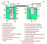
The number 1 page is the schema of the tanks with the letter references in order to refer from each page what is that part.
The no number page is the module for the fuel pump that increase or decrease the speeed of the pump and works closely with the engine module for the needs of the motor. this module locaion is on the driver side behind the rear fender front wheel housing,
The number page 2 is a drawing of the thanks with all parts together. ( including the emission solenoid valve )
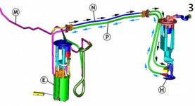
The number page 3 is showing how fuel circulate in both thanks.
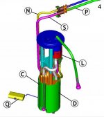
The number page 4 is the fuel pump it self
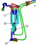
The number page 5 is the emission device.
Enjoy the reading hand a head storm.
IAN
![A2 fuel line control module$_57[1] (3).jpg A2 fuel line control module$_57[1] (3).jpg](https://www.xlr-net.com/forums/data/attachments/5/5424-60fcea5f9a2e901145ce8c2c5580da2d.jpg?hash=YPzqX5oukB)
![A1 fig3c5fuel[1].jpg A1 fig3c5fuel[1].jpg](https://www.xlr-net.com/forums/data/attachments/5/5425-2cbc38bb32aafc37c79843b143df66a8.jpg?hash=LLw4uzKq_D)
Many of us have asked informations about the XLR/Corvette fuel tanks.
Attached are drawings of the driver and passenger thanks explainings with references letters the actual parts location, its explain by it self and will help the members how they functions in the system.
The number 1 page is the schema of the tanks with the letter references in order to refer from each page what is that part.
The no number page is the module for the fuel pump that increase or decrease the speeed of the pump and works closely with the engine module for the needs of the motor. this module locaion is on the driver side behind the rear fender front wheel housing,
The number page 2 is a drawing of the thanks with all parts together. ( including the emission solenoid valve )
The number page 3 is showing how fuel circulate in both thanks.
The number page 4 is the fuel pump it self
The number page 5 is the emission device.
Enjoy the reading hand a head storm.
IAN


![A2 fuel line control module$_57[1] (3).jpg A2 fuel line control module$_57[1] (3).jpg](https://www.xlr-net.com/forums/data/attachments/5/5424-60fcea5f9a2e901145ce8c2c5580da2d.jpg?hash=YPzqX5oukB)
![A1 fig3c5fuel[1].jpg A1 fig3c5fuel[1].jpg](https://www.xlr-net.com/forums/data/attachments/5/5425-2cbc38bb32aafc37c79843b143df66a8.jpg?hash=LLw4uzKq_D)


