Welcome to the Cadillac XLR Forums!

The end-all DRL modification

MPRCTCL

Seasoned Member
Joined
Apr 18, 2018
Messages
222
Location
Michigan
My XLR/V(s)
2008 Crystal Red XLR-V
Checked one of my winter projects off the list. I understand the need to get those high-wattage bulbs out of my DRls before the lenses are damaged, but I couldn't just stop there. I wanted switchback bulbs, but wanted them to operate totally transparently and as designed, not requiring the parking lights or anything to be on. Maybe there was an off the shelf option, but I couldn't find one so I made my own. I designed a circuit, fabricated boards, and hogged-out some cases. Yesterday, I finally got the time to put the pieces together. Thought I'd share some pics.

When you drop the transmission into drive, the DRLs come on. With my circuit, they light amber for (literally) one second, then ramp-up to full brightness white light. Turn signals (or hazards) flash amber (without the white) and then the white ramps up again after the turn signal ends.

Here's the board I designed an built. Probably over-designed, but I didn't want problems with vibration. It has a built in self-resetting fuse in case anything gets weird.
IMG_7861.jpg


I used the silicon seals from weatherproof connectors and made blocks to hold them on a standard project box. These provide both water-resistance and some flex so the wires don't fatigue with vibration.
IMG_7863.jpg


Here's everything together, including new socket. Ignore the resistor mount, as it had to be re-worked to fit in the fender better.
IMG_7865.jpg
IMG_7864.jpg


Here's the improved resistor mount. The plate has counter-bored holes that attach to the HID module screws.

IMG_7876.jpg
IMG_7877.jpg


I was going to post a video of operation, but its hard to shoot that video on my iPhone because the flashing lights wash out the color as it tries to auto-compensate for brightness. Oh well!

Next? probably playing with the Class 2 bus to see if I can manipulate the HUD with a (future) after-market radio upgrade.
 
move that heat sink. it will melt the housing. Plus add heat to the control module that already burns out from too much heat.Even the ones mounted inside the fender wells about 1 to 2 inches away from the fiberglass have been know to melt the smc inner structures.

ok reading again you may have moved it. sorry to jump quick but I know what that will do seen some nice lights ruined. I just installed led bulbs by themselves and they work just like they should. I have no problem with them on when driving. Help make the little tiny side light look better. they blink just like they should without any other mods.
Not sure about your circuit board but it does look fantastic just don't get what its supposed to do?
 
Last edited:
So, to clarify, your bulbs are white for DRL and blink amber? Because the switchback bulbs I bought would not do that without the extra circuitry.
 
Impressive! Nice work getting a fix in before the lenses yellow!
 
I sure don’t have the knowledge to do any technical critique but WOW! That’s impressive!
 
I went the easy route with mine. I installed 10K LED bulbs for the DRLs and rerouted my wiring so the side marker lights (under the orange lenses on the sides of the headlamp housing) are my turn signals.
 
Could someone explain what the issue with the stock DRL's and/or turn signals?
 
stock driving lights sit to close to the outer lens and melt it. giving what some call cataracts. 04 and 05 got so hot as to melt the bulb holder . you see some with new bulb holders spliced in correctly with heat shrink tape. that's a GM recall fix that still kept the bulb to close tot he outer lens. Bulb holder improved in 06-09 but still melted the outer lens. LED bulbs are much cooler but to keep them from flashing too fast (some do some don't) you add a resister that gets hot to the system to slow the LED bulb flash down.
 
Ah ok. Yes, switching to LED's will bring the temps way, way down. Appreciate the info.
 
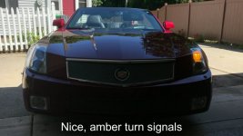
I got into a conversation in another post about how I wanted my DRLs to work and decided I should post some pictures to clarify why I needed the additional circuitry.

With the headlights and DRL off, the turn signals are amber. Just like factory (but cool LED bulbs.)

Snapshot - 2.jpg

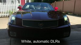
In gear, the DRL come on white. The bulbs I got come up from dim to bright to simulate an incandescent bulb.

Snapshot - 3.jpg

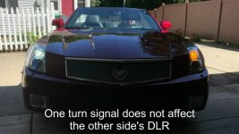
With the DRL on, the turn signals are amber and independent. They don't alternate between amber and white.
More like 2018 models are.

Snapshot - 4.jpg

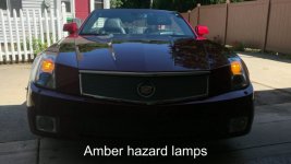
Hazard lights are amber and do not alternate between amber and white.
Snapshot - 6.jpg

PM me if you want to know which bulb I used. I'm not listing it here now so anyone who isn't reading the whole thread won't buy them thinking they do what mine do without the additional circuitry.
 
I thought about this for a while and figured out a simple way to do this, just a simple timer relay. I got a couple off eBay for like $2.32 each. If you don’t mind cutting up the wiring, it can be done for this plus a 3 way socket(about $3 each) LED switchback bulbs($60 I used good ones) and load resisters(about 5$ Each). You can get plug in adapters for current sockets for about another ($6 each) if you don’t want to cut up wiring. And probably a box or housing for another $5each. Been running a test setup in the car all summer and seem to hold up well without the relay circuit being in a box.
 
I thought about this for a while and figured out a simple way to do this, just a simple timer relay. I got a couple off eBay for like $2.32 each. If you don’t mind cutting up the wiring, it can be done for this plus a 3 way socket(about $3 each) LED switchback bulbs($60 I used good ones) and load resisters(about 5$ Each). You can get plug in adapters for current sockets for about another ($6 each) if you don’t want to cut up wiring. And probably a box or housing for another $5each. Been running a test setup in the car all summer and seem to hold up well without the relay circuit being in a box.
In essence, that’s what my circuit is doing, but without relays. Myself, I don’t want to take any chances with mechanical parts or vibration, but that’s just the engineer in me. Good job!
 
You don't need to use a resistor. It's around 6 to 7 volts RMS when the turn signal is used and around 11v or greater (RMS) when using the DLR's. A voltage comparator circuit tracking RMS voltage (70 mA) will work.
 
So you’re averaging the voltage over a longer period... interesting. I’ll look at that. Without thinking too hard, it seems like that may have some hysteresis issues at the beginning or end of a flash sequence given the duty cycle.

I don’t see what that has to do with the resistor, though. The resistor is to satisfy the vehicle’s burnt-out bulb sensing mechanism which used a simple current consumption measurement.
 
Last edited:

Cadillac XLR Forums

Not a member?  Join now!  It's Free!

Learn more about Supporting Membership

Win 2 Supercharged Cadillacs!

Win both supercharged Cadillac Vs!

Supporting Vendors

Taput Tunning LLC

Top Hydraulics

Cadillac XLR Registry

Click here to enter the official Cadillac XLR and XLR-V Registry
Back
Top Bottom